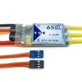
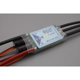
This prop position sensor works with all YGE ESCs larger than the 35 LVT. It allows the stopped prop position to be set, so the blades always stop and fold in th same position (eg horizontal).
German Manual translation:
Please note that propeller positioning is only available from controller firmware V1.03527.
The latest PC software is also required.
The controller must be configured to mode 4 (glider with brake). Then you can in the area
“Advanced” positioning can be activated with a tick. These can now also be found here
Fine-tune speed, hold time and power. We strongly recommend checking this out first
Leave default values. In particular, if the positioning performance is too high, it can generate too much heat
In the worst case scenario, this can lead to a defect in the controller.
Positioning speed (default value:): The speed can be adjusted with this parameter
with which the motor rotates during positioning. Please note that too high a speed
Inaccuracies and thus the position cannot be recognized.
Positioning hold time (default value:): Here you can set how long the hold time after successful
Positioning should be active. We recommend that you do not choose this time too long (max. 1 minute), as this will result in
a higher power loss occurs. After the specified holding time, the normal engine brake is applied
switched. This can result in high airspeed positioning with fixed propellers
is not maintained. With folding propellers the position should be maintained even at high speed.
If it needs to be positioned again, a short burst of gas is sufficient.
If the propeller is moved out of position within the holding time, the controller begins to position again.
Positioned performance (default value:): This value should only be increased step by step if
the motor with the standard value does not rotate during positioning and, for example, only jerks back and forth. Important! One
Positioning performance that is too high can lead to excessive heat generation and, in the worst case, to a defect in the controller
lead.
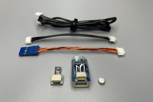
Assembly instructions Hall sensor and magnet for propeller positioning
? Find a suitable place for the sensor on the engine frame. (For now just fix it, not yet tight
Glue in.) The sensor should be placed at a distance of approx. 2mm on the inside of the spinner collar
become.
? Rotate the spinner/propeller to the location where it will be positioned later.
? Mark the center of the sensor on the spinner.
? Stick 1 magnet on the inside of the spinner in the area of the Hall sensor. For now with thin
Fix the double-sided adhesive tape, then stick it later with e.g. UHU-Plus. Recommended magnets, depending on
Spinner diameter, 2-5mm diameter and 1-2mm thick. Material N20 to N45, available e.g. from Amazon
or www.supermagnete.de
? The smaller the spinner diameter, the smaller the magnet must be. For one
For a spinner diameter of e.g. 38mm, a magnet with a diameter of 3mm and a thickness of 1mm has proven useful.
The unbalance caused by the magnet is not noticeable. If necessary, attach a non-magnetic one of the same size
Metal plate (e.g. screw head) on the opposite side in the spinner.
? Attention: Mount the model in a secure stand. First tests always without propellers. Any
Test with prop at a safe distance and not in the work area where parts can fly around.
Make sure the prop can rotate freely.
? The yellow LED on the controller lights up when the magnet is in the detection range of the Hall sensor.
? When the magnet is detected, the motor first moves over the sensor, turns around and stops
then stand approximately in the middle of the magnet. This area extends over approximately 30°
entire turning circle. Using the example of the 38mm spinner diameter, this is a range of approx.
10mm. Larger spinners have a correspondingly smaller rotation range.
Possible errors and their remedies:
? The engine does not stop (oscillates back and forth). The yellow LED goes out and lights up again
in the middle of the sensor and goes out again shortly afterwards. This is where the shading occurs
Magnetic field lines in the middle of the sensor. To remedy this, the magnet needs to be approx. 1-2mm outside
of the rotation circle of the sensor center.
? The motor only moves back and forth 1-5°. The positioning performance needs to be increased somewhat here. If
If no improvement can be achieved, the motor is incompatible and does not work with the
Positioning.
? The motor continues to rotate slowly and does not stop. The yellow LED always stays off.
? Sensor does not recognize the magnet.
? Distance too large.
? Magnet missing.
? Magnet too strong or too weak.
? Sensor defective.
? If no sensor is detected, the engine stops after 60 seconds.
Structure with round magnet:
Below are assembly instructions for high-speed motors. e.g. Leomotion LEO 80XX
Attach the magnet with double-sided adhesive tape and resinate it later.
Distance to sensor 1.5 ... 2.5mm.
Mounting magnet/sensor in the middle, offset max. +- 1 mm axially and radially. So all installation tolerances are not critical.
Here again only 1 magnet is used
 447821351341
sales@hyperflight.co.uk
Contact Form
447821351341
sales@hyperflight.co.uk
Contact Form